Carbon Fiber Sandwich Monocoque Chassis Design and Manufacturing
12 kg carbon fiber sandwich monocoque chassis graduation thesis project developed for TEKNOFEST Efficiency Challenge, covering CAD design with SolidWorks, composite finite element analysis with ANSYS ACP and vacuum bagging manufacturing on a moldless flat table.
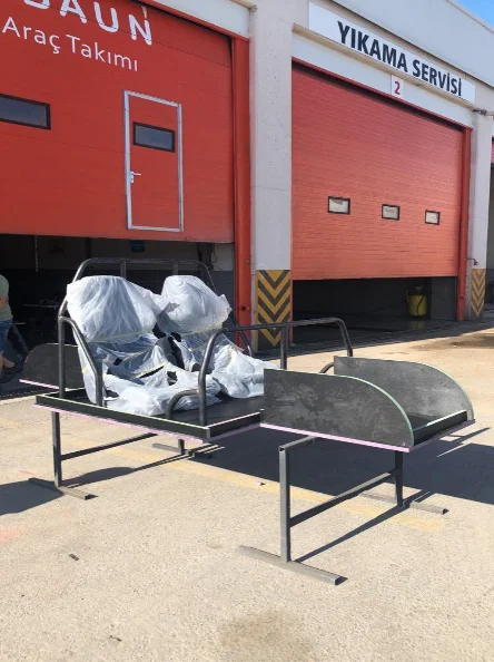
🏎️ Final Thesis · TEKNOFEST Efficiency Challenge
Carbon Fiber Sandwich Monocoque Chassis for Electric Vehicle
A holistic development study extending from concept design to physical product: bathtub type monocoque design with SolidWorks, composite finite element analysis with ANSYS ACP, material selection and manufacturing with vacuum bagging method on a moldless flat table.
Project Imprint
Problem and Approach
The metric evaluated in efficiency races is the distance traveled per unit energy. Vehicle mass is the most direct variable in this equation: each kilogram increases both rolling resistance and the energy required for acceleration. Therefore traditional space frame instead of a pipe chassis, which spreads the load on the surface sandwich monocoque body is preferred.
The decision was made to sacrifice cost and ease of repair under student team conditions. weight and rigidity given in his favour. In addition, in order to avoid the cost and time burden of making a mold, the method of producing it on a flat table and shaping it later was chosen (see the Production section for details).
Load Path: What Does the Chassis Carry and What Does It Not?
The drive architecture of this vehicle directly determined the design constraints of the chassis. torque hub engine It is produced directly on the wheel with; There is no shaft, differential or drivetrain passing through the chassis. Therefore the chassis is a torque is not the reaction path. This explains why the rear extension in particular can be designed thin and light.
✓ Loads carried by the chassis
✗ Loads that do not pass through the chassis
Design (CAD)
Geometry in SolidWorks environment, relative to midplane mirror It was established symmetrically. This both simplified the model tree and enabled the use of symmetry in the analysis.
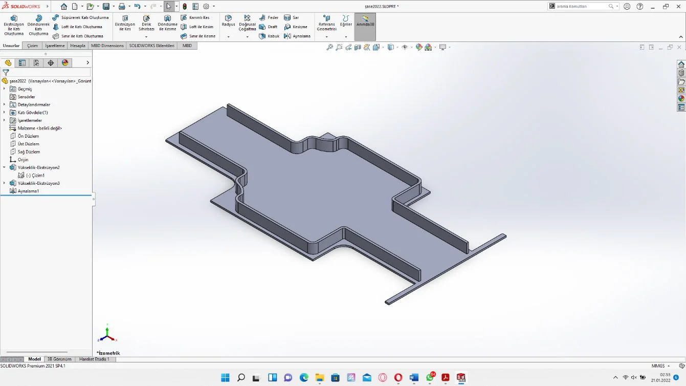
Figure 1 — Simple bathtub geometry. The plus-form silhouette and peripheral raised edges are visible.
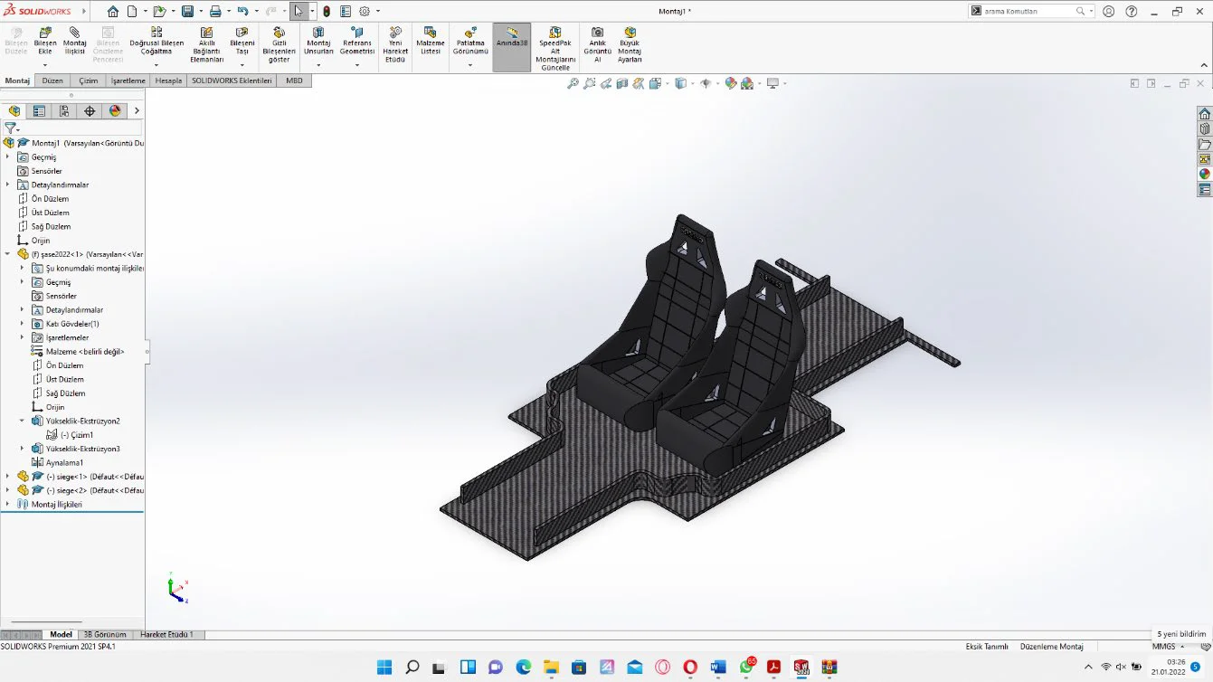
Figure 2 — Ergonomics verification with Sparco seat layout and carbon texture cladding.
Top View Architecture
The silhouette is in plus (cross) form. Each zone contains enough material to meet a single function; unnecessary surface is directly unnecessary weight.
▲ Vehicle front facing up · peripheral dashed line = raised edge area
Why Lifted Edges?
Peripheral raised edges on the CAD model are not cosmetic. The material's contribution to bending strength decreases as it moves away from the neutral axis. cubed by height increases proportionally. Moving the same mass to the edges instead of a flat plate turns the chassis into a beam.
Doubling the height increases the bending resistance by approximately eight times.
Note: Since no formwork was used, this height was achieved with box profile strips that were produced and glued separately to surround the cured flat panel (see Production section).
Mechanics of Sandwich Structure
This is the core idea of the project: separating two thin carbon fiber shells with a low-density PVC foam core. The shells carry the tensile and compressive loads, and the core carries the shear load and keeps the shells at a constant distance.
📊 Why 20 mm Core?
Bending stiffness of a sandwich panel, shell thickness t and distance between shell centers d. for approximately D ≈ E·t·d² / 2 is proportional to . In this study, d ≈ 21 mm, t ≈ 1 mm.
If we used the same amount of carbon fiber as a coreless, one-piece 2 mm laminate, the moment of inertia would only be I = (2mm)³/12 it would be. Separating the shells by 20 mm increases the bending stiffness at the level of two orders (hundreds of floors) while increasing it only adds approximately 1 kg of foam per square metre. The whole logic of the sandwich structure lies in this ratio.
Material Selection
Weaving Type Decision: Plain or Twill?
✅ Plain — Selected
The most frequently interlocked weaving in which the weft and warp threads pass symmetrically, 1 bottom / 1 top.
- High thread crimp → dimensional stability
- Minimal fiber slippage on large flat surfaces
- Fiber angles are maintained under vacuum
❌ Twill — Not Preferred
Weaving with a characteristic diagonal pattern, with 2 under / 2 over passes.
- It fits complex curves better (drapability)
- But the fiber is easy to slip
- There is no advantage in this geometry, there is a risk
Layer Orientation
Fibers oriented in one direction are only strong in that direction. The layers are stacked at different angles to ensure that the structure resists in all directions.
0° / 90°
It absorbs axial tension-compression loads during braking and acceleration.
+45° / −45°
It absorbs torsion loads occurring in bends.
Quasi-isotropic stack
Similar behavior in in-plane directions with the 6-layer balanced stack.
Finite Element Analysis (ANSYS ACP)
Since composite materials behave directionally (anisotropic), a classical isotropic static analysis is not sufficient. For this reason, analysis allows for layer-by-layer identification. ANSYS ACP (Composite PrepPost) It was installed with the module.
⚠️ First Iteration: Critical Finding
to the surface Uniform reference pressure of 0.1 MPa In the first analysis applied, in the middle region of the chassis 154.69mm deformation was calculated. This load does not represent a real driving scenario, but a common reference chosen to compare design variants in the same condition. The result clearly showed that the initial geometry did not have sufficient stiffness in the middle region.
✅ Revision
In line with the analysis results, we returned to the SolidWorks model and added structural reinforcements to the middle area and reviewed the peripheral edge heights. Production started with this revised geometry.
Resin Calculation
Too much resin in the composite means weight. Less resin means dry area and delamination. Consumption is therefore not left to guesswork: for fabric it is based on surface area, for foam it is based on surface area. manufacturer's lay-up table was calculated using .
📋 Hand Lay-Up Resin Consumption for Airex PVC Foams
| Foam Type | g/m² | oz/sq.ft |
|---|---|---|
| R63.50 | 100 – 200 | 0.33 – 0.65 |
| R63.80, R63.140 | 50 – 150 | 0.16 – 0.50 |
| R82 | 200 – 300 | 0.65 – 1.00 |
| C51 | 200 – 300 | 0.65 – 1.00 |
| C70.40 – C70.90 ← C70.48 used | 200 – 300 | 0.65 – 1.00 |
| C70.130 – C70.200 | 100 – 200 | 0.33 – 0.65 |
| C71 | 150 – 200 | 0.50 – 0.65 |
| T90/92 < 130 kg/m³ | 200 – 300 | 0.65 – 1.00 |
| T90/92 > 130 kg/m³ | 150 – 250 | 0.50 – 0.82 |
| T10 | 200 – 300 | 0.65 – 1.00 |
Total Resin Casting: 7 kg
| Mixing ratio | MGS L160 : H160 = 100 : 25 |
| Pot life | ≈ 45 minutes → prepared separately for each layer |
| measurement | Weighing with precision scales |
| Edge profile gluing | A separate recipe: structural epoxy adhesive (not included in the above 7 kg) |
The 45-minute pot life of the resin was the constraint that determined the production rhythm. Instead of preparing a large amount at once, a separate mixture was made for each layer; This enabled homogeneous wetting before gelation began.
Production: Vacuum Bagging on Flat Table without Mold
The method uses atmospheric pressure like a press. When the air inside the bag is drawn out, the outside pressure of about 1 bar compresses the laminate; Excess resin is absorbed into the blanket, air pockets are removed. The result: higher fiber volume fraction and lower weight.
Instead of having a shaped mold made, sandwich panel on a flat work table cured; cross (plus) silhouette and raised edge profile after curing cutting and pasting It was reached with. This approach kept in line with student team resources by sacrificing pattern cost and time.
Bagging Stack
The perimeter was sealed with sealing tape. Pleat was applied to prevent the bag from tearing.
Curing time: 1.5 days under vacuum
Production Steps
Work Surface Preparation
The 3.5 × 1.7 m flat wooden table was cleaned and the release film was laid on it. It is not a shaped mould, but a completely flat laying surface; The purpose was only to ensure that the panel separates without adhesion after curing.
Lower Shell — 3 Layers
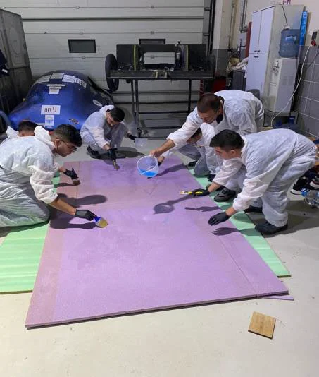
The first layer of carbon fiber was placed on the release film on the table. Epoxy prepared in a ratio of 100:25 was poured on a sensitive scale and applied homogeneously to each area using the hand lay-up method. The same process was repeated for 3 coats.
Core Layout
The PVC foam core, saturated with the amount of resin calculated from the Airex chart, was laid flat on the bottom shell. The amount of resin allocated for foam was 1.5 kg.
Upper Crust — 3 Layers
The remaining 3 layers were laid on the carbon fiber foam using the same method and resined. Thus, a flat, rectangular 22 mm sandwich panel is completed.
Auxiliary Layers
Peel fabric, escape bag and vacuum blanket were laid on the laminate, respectively. Each layer has a separate task: clean separation, resin migration and absorption of excess resin.
Bagging and Vacuum
Sealing tape was applied around the perimeter, a vacuum bag was placed, and tapering was applied at the corners to prevent tearing. Then, the air in the bag was removed with the help of a compressor.
Curing and Separation from the Tray
The structure was left to cure under vacuum for 1.5 days. At the end of the period, the bag was dismantled and the flat, rectangular sandwich panel was separated from the table. At this stage the panel was not yet in final chassis form.
Shaping (Cutting)
The cross (plus) silhouette taken from the CAD drawing was marked on the cured flat panel and the part was cut along this line and brought to top view geometry.
Edge Profile Bonding and Final Weight
Separately produced box section strips were mounted with structural epoxy adhesive around the perimeter of the panel, cut to meet the raised edge height in the CAD model, and allowed to cure. Final weight weighed after assembly is completed: 12kg.
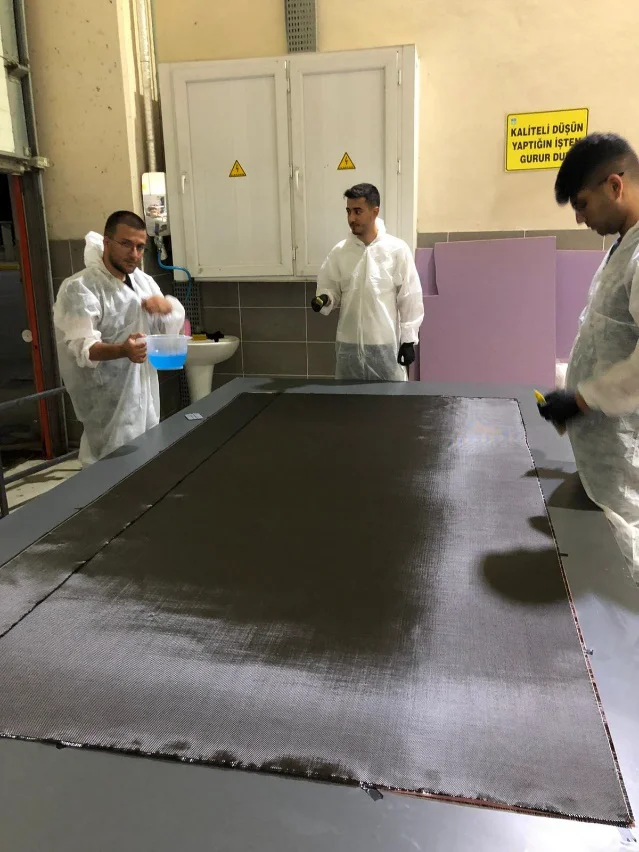
Resining of layers by hand laying on a flat table.
Saturating the foam core with the calculated amount.
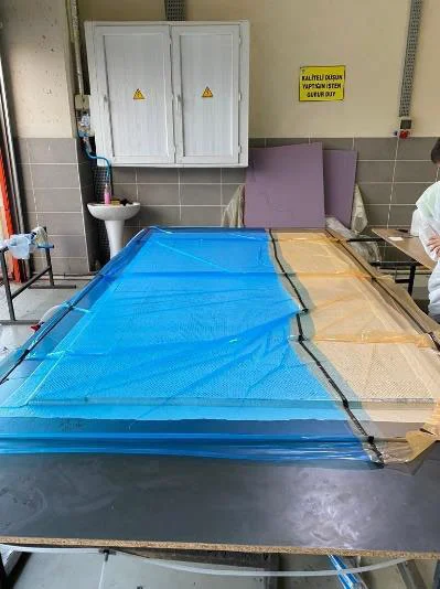
Curing under vacuum on a flat table (1.5 days).
Chassis with cut and glued edge profiles, ready for assembly.
Conclusion
Weighed values of the shaped and assembled chassis
|
12
kg
Final Weight
|
22
mm
Sandwich Section
|
1,5
day
curing
|
Project flow
The project was a holistic study in which all steps were carried out personally, from concept to design, from simulation to revision and physical manufacturing on a flat table without moulds. The carbon fiber sandwich monocoque body was made ready for racing and integrated into the vehicle.
What I Learned and the Limits of Working
1. Analysis works as soon as it changes the design. The large deformation value in the first iteration was not a failure, but the most valuable outcome of the project: it told us that we needed to change the geometry before going into production.
2. Knowing the load path is material saving. Having the drive in the hub engine meant that the rear overhang was merely a body carrier and not an engine mount. This awareness allowed avoiding unnecessary reinforcement in that area.
3. In composite, the calculation is made within the production. The weight is under control when the amount of resin is read from a table value and weighed on a scale; Not when the decision is made by eye.
4. Manufacturability is a constraint of design. The 45-minute pot life of the resin directly determined the layer stacking plan. A laminate that's right on paper isn't right if it's not workable.
5. Moldless production divides the geometry into two: flat curing + post-forming. Instead of investing in a shaped mold, producing a flat panel, curing it, then cutting and gluing the edge profile to reach the final form is compatible with the student team's budget; However, this created additional bond lines in the edge areas.
⚠️ Limits of Work
The analysis was performed under a uniform reference pressure chosen to compare design variants; It is not a strength verification that is the basis for certification. The ANSYS ACP model represents edge regions as a continuous (monolithic) shell; Since these areas in the real part were created with box profiles that were subsequently glued, the stress concentration at the bonding interfaces and bond line strength were excluded from the scope of analysis.
No torsional stiffness measurement or sample-based mechanical testing (three-point bending, shear test, adhesive connection tensile test) was performed on the produced panel. For a true validation, the next step is to prepare coupon samples from production residues and compare the measured mechanical values for both the laminate and edge bonding bond with the analysis inputs.
Software, materials and methods used within the scope of this project:
Related Projects
View All ->
SkyTrace - Python Based Rocket Orbital Simulation
Parametric rocket simulation developed with Newton's laws of motion and aerodynamic drag principles....
View Project arrow_right_alt
Real-Time Tank and Armored Vehicle Detection with Spotter UAV-YOLOv8
YOLOv8-based autonomous threat detection system for the defense industry. Real-time detection of tan...
View Project arrow_right_alt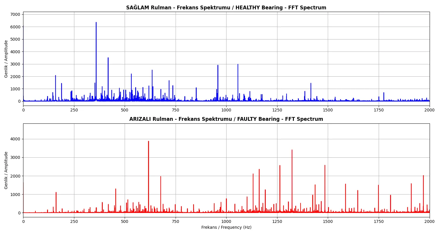
Bearing Fault Detection - Predictive Maintenance and Machine Learning Project
Project to detect bearing faults with 100% accuracy using CWRU vibration data with FFT signal proces...
View Project arrow_right_alt